#what does a mosfet
Explore tagged Tumblr posts
Visit Tumblr Blog
Explore Tumblr blogs with no restrictions, modern design and the best experience.
Last Seen Tumblr Blogs


Fun Fact
Women make up for the other 50% of Tumblr’s audience.
Text
https://www.futureelectronics.com/p/semiconductors--discretes--transistors--mosfets/nds331n-onsemi-1014174
Power mosfet, mosfets, mosfet switch, mosfet gate, super junction mosfet
Single N-Channel 20 V 0.5 W 5 nC DMOS Surface Mount Mosfet - SOT-23
#Onsemi#NDS331N#Transistors#Mosfets#Power mosfet#mosfets#mosfet switch#mosfet gate#super junction mosfet#what does a mosfet#low voltage mosfet#Surface Mount Power MOSFET#high voltage mosfet#mosfet uses#audio mosfet
1 note
·
View note
Text
https://www.futureelectronics.com/p/semiconductors--discretes--transistors--mosfets/std65n55f3-stmicroelectronics-5034919
Linear mosfet, small signal mosfet, power mosfet, Transistors mosfet
N-Channel 55 V 8.5 mOhm Surface Mount STripFET Power MosFet - TO-252
#Transistors#Mosfets#STD65N55F3#STMicroelectronics#Linear mosfet#small signal mosfet#power mosfet#Transistors mosfet#what does a mosfet do#Mosfet module#audio mosfet#super junction mosfet#mosfet circuit#switch#types of mosfet
1 note
·
View note
Text
https://www.futureelectronics.com/p/semiconductors--discretes--transistors--mosfets/buk9y19-75b-115-nexperia-5046162
What does a mosfet do, audio mosfet, Digital transistors, power mosfet
BUK9Y19 Series 100 V 19 mOhm SMT N-Channel Logic Level MOSFET - LFPAK-56
#Transistors#Mosfets#BUK9Y19-100E#115#Nexperia#what does a mosfet do#audio mosfet#Digital transistors#power mosfet#mosfet circuits#Power regulators#gate#linear mosfet#applications#high current mosfet#Mosfet switch
1 note
·
View note
Photo

audio surplus effects - OK doomer
“Has one unlabelled external control. What does it do?! Who knows! Turn it and find out! Also it has a massive knob. And just to piss you off, the only other control (a low-pass filter trimpot) is internal so you have to unscrew the bottom of the pedal to access it ... And for the nerds, Ok Doomer is a result of multiple cascading mosfet gain stages collapsing in on themselves running into a specifically voiced tonestack producing a high-gain fuzz/distortion designed to make you play the same riff for over an hour until you drop out of life with cramp in your hand.”
cred: audiosurpluseffects.bigcartel.com
79 notes
·
View notes
Text
Not Bad.
In my wandering around the internoise I find a lot of errors. Errors of fact which in turn lead to confusion and poor assumptions.
I often comment on two dichotomies in the audio world. One is of course tube versus solid state electronics. The other is digital versus analog recording and play back. In both areas either side can provide excellent performance.
I have and appreciate both digital and analog recordings.
I have and appreciate both tube and solid state electronics.
Each are different. I have preferences. Neither is inherently bad.
Other people get wound up and committed to this side or that. Recently I read a person saying that vinyl albums have a limited frequency response so they are obviously inferior just for that. London ffrr recordings claimed up to 16khz which is pretty good, and CDs are good to 22khz ( 1/2 of 44khz or the Nyquist frequency) end of debate, so there.
The CD could easily produce up to the theoretical limit of human hearing. I think all digital methods have a similar limit as even with very high carrier frequencies they are filtered to pass nothing above 20khz. That is to facilitate low slopes in the output filters of Class D amplifiers for example. Academic for me as my hearing quits at 12 khz.
But what is the actual limit of LP frequency response? How about 45 khz. Back in the 1970s several companies tried to make quadraphonic sound. They encoded rear channel signals using a high frequency modulation on top of the normal music signal. It did not work all that well, and there were several competing standards and nobody won. But it did fundamentally work.
They produced stereo phono cartridges and LPs with 45 khz information on them using basically the methods used before and since. They made LPs with ultrasonic signals on them. They developed styli that were finer to track this information such as the Shibata which are still made.
My Signet TK7E cartridge was rated to respond to 45 khz. The better Grado cartridges also go that high. The top of the line Grado is rated to 70 khz. This is vinyl technology we have here with at least double the frequency response of digital methods. So no vinyl is not inferior in terms of frequency response potential.
We are of course talking about best case potential, but they did put this stuff out in the market. It actually worked.
Oh CDs have superior dynamic range, but like 20khz high frequency limit can you even use it? If the information is not on the recording does it even matter? LPs have enough for 95% of the time. I have a single CD with an extreme dynamic range where the quiet is very quiet, but turning it up to hear that part of the music makes the loud bit deafening. (KODO)
More recent digital methods have even better dynamic range. They actual use for that is in the recordings, not the playback.
Analog versus digital quality depends on production more than potential. In terms of best neither is. Oh MP3s suck generally as the priority there was compactness not quality. CDs, DSD, High res streams are fine.
And as far as tube versus solid lumps of semi-conductors well it is kinda the same. Computers and Class D amplifiers use MOSFET materials and those run at gigahertz. There are consumer vacuum tube amps that respond up to 100khz fine, and go down to 10 Hz as well. Either technology has far more potential performance than anyone can use.
Both types can have very low distortion. At normal listening levels the percentage is minuscule. Different voice and such is real but due to other things which to me are almost like black magic. My freshly retubed ARC amp sounds far more clear than before. It is still different than my old SS amp.
This stuff is not bad.
2 notes
·
View notes
Text
Search valued Stereo power amplifier to experience complete streaming requirements
Do you want to achieve better sound in your music and audio signals? However, gaining this outcome is not easy for everyone, as some music devices only perform audio functionality for a while. If you face a low audio facility, then you go ahead with technological advancement. So, you must confirm your goal and try to audio better through using amplifiers. Throughout the marketplace, you come across many amplifiers. But you need more certainty about how to add sound.
Refrain from making the decision to buy a power amplifier. Instead, take a brief review and analysis to see how much it improves overall performance in your self-prepared game series. As it converts the power signal into a higher one, sufficient improvement in your live streaming is about to happen. No matter what power amplifier you use, it is the part of the subwoofer speaking system that is concerning.
What do you expect from a power amplifier?
Using the fine-grade amplifier makes you quite close to enhancing sound quality. After all, you must experience a better sound experience regardless of operation. But, you have the technical expertise to reach one conclusion to select the best amplifier name. So, you should keep key points in mind when choosing the best version of the stereo power amplifier. It must contain the signal gain, efficiency, and output power.
If the numerical value of one amplifier is greater than the other, consider the next one. The overall strength of the Power amplifier is measured in watts. The high watts indicate that they have been strengthened more. If you have to purchase the best quality amplifier, then you focus on its characteristics. Let us check how Amp IV can seem better than general-purpose power amplifiers.
Characteristic of Amp IV
Dual Mono Reference Power Amplifier
High damping factor availability for controlling the speaker
20 selected MOSFET output transistors
WBT loudspeaker terminal
Professional protective circuit
Voltage gain 250 DB
When you connect with a media-rich industry, you are in the prime of distributing multiple audio systems according to your needs. After that, app-based functions are quite helpful for distributing music on a wide range of Wi-Fi networks. Using the streaming amplifier, transforming network music is not difficult even though there is no multiple-box availability.
Keep your audio quality up-to-mark according to your business. But, you need the sure affirmation to end your search at which destination. While settling business in Germany, you can search Germany made audiophile speakers to achieve a fruitful sound quality experience. The sound quality should be such that it does not compel the listener to leave your streaming due to low pitch audio. No matter what audiophile component you require, our destinations are equipped with all the components to fulfill your needs. Visit our website to get the Amplifier details.
YouTube channel link: https://www.youtube.com/@accusticarts955
youtube
#audio power amplifier#power amplifier online#stereo power amplifier#germany made audiophile speakers#power amplifier amp iv#stereo pre amplifier#Youtube
1 note
·
View note
Text
Between Analog and Digital: Comparators

Sometimes, there's a need to compare two voltages. A special circuitry stage exists to serve just this purpose—a comparator. Today, I will tell you all about comparators and show a few examples of their use.
What is the field of application for comparators? — It is literally any device; many microcontrollers have built-in comparators of their own!
Remember our post on PWM (https://teardownit.com/posts/pwm-led-dimmer)? That circuit used as many as two comparators—U1A and U2B.

What could be simpler than a comparator? It compares two voltages at its two inputs, and based on the result of this comparison, it connects its output to the positive or negative power line.
When the voltage at the non-inverting input is higher than at the inverting input, it will be a positive supply voltage line and, accordingly, a high voltage level, a logical one. Otherwise, it will be a negative power line, a low level, or a logical zero.
Why does the comparator look like an op-amp in the diagram? Most often, this is the operational amplifier.
U1A switches the timing capacitor C1 to charge or discharge, depending on the voltage at point C, which comes to the non-inverting input of the comparator through resistor R10.
Let me draw your attention to resistor R9, as it is of great importance in this scheme.
We are accustomed to connecting a resistor between an op-amp's output and the inverting input to set the gain. This is negative feedback.
The output of U2A is connected to its inverting input. We should recall two fundamental principles of the operation of an operational amplifier: virtually no current flows through its inputs, and the output voltage, with negative feedback present, will be such that the voltages at the inverting and non-inverting inputs are equal.
Thus, the voltage at the output will equal the voltage at the non-inverting input. We've got a buffer—a voltage follower.
Why do we need such a buffer? Because the input impedance of the operational amplifier is very high, and the output impedance is low.
That means we can transmit input voltage to the load that requires a significant current and simultaneously not overload the circuit generating this voltage and not distort its operation.
And here is a small part of the Fulltone OCD guitar pedal circuit from our post about DIY Dumble-like sounding MOSFET Overdrive. The operational amplifier no longer repeats but amplifies the input voltage.

For simplicity's sake, let's ignore capacitors, although they contribute to impedance. We have to understand the core principle.
The amplifier input is the left terminal of resistor R10. To pull up the non-inverting input of the op-amp to virtual ground, which is half the supply voltage, resistor R12 is used.
R10 and R12 form a voltage divider. The voltage at the non-inverting input will equal the input multiplied by R12 / (R10 + R12) = 220 / 230 = 22/23.
22/23 is almost 1, so we'll assume that the voltage at the non-inverting input, and therefore at the inverting input, is equal to the input.
R13 and R11 are also voltage dividers in the feedback circuit of the operational amplifier. The output voltage will equal the input voltage multiplied by (R13 + R11) / R11 = 189 / 39 = 4.85. Or 4.64, if you insist on multiplying by 22/23.
Let's get back to the PWM regulator circuit. Here, we have the same voltage divider but in a stage of positive rather than negative feedback! And it is assembled with resistors R9 and R10.
Almost no current flows through the inputs of an op-amp; it only goes through R9 and R10. And since this is the same current (let’s denote it as 'I'), we can write the equations of Ohm’s law for resistors R9 and R10.
Let's say the input voltage at the correct pin of R10 is Uin, and the output voltage at the output of U1A is Uout. Call the potential of the non-inverting input U1A 'U', and we obtain the following equations:.
I = (Uout - U) / R9 I = (U - Uin) / R8
Next, we transform our equations to calculate the dependence of U on Uin.
(Uout - U) / 5.6 = (U - Uin) / 2
For simplicity, let's round 5.6 up to 6.
(Uout - U) / 3 = U - Uin Uout - U = 3U - 3Uin 3Uin = 4U - Uout U = 3/4Uin + Uout / 4
To understand what Vout might be equal to, we need to refer to the datasheet for the LM358 chip from Texas Instruments.

Our PWM controller has a bipolar power supply of +12 V and -12 V, for a total of 24 volts. These are our power bus voltages. However, due to its design characteristics, the deviation of the operational amplifier's output voltage also depends on the output current.
The load U1A is a parametric voltage stabilizer based on a two-anode Zener diode assembled from two conventional Zener diodes connected in a back-to-back series.
The forward voltage across the Zener diode at the standard shunt regulator current is 0.7 volts. Then, the correct pin of R8 will have a voltage of 5.8 volts with a plus or minus sign, depending on the polarity of the U1A output.
That means the current through R8 will be about 5 milliamps. Then Vout can be somewhere between + (12 - 1.5) = +10.5 V and - (12 - 0.75) = - 11.25 V.
So, when the logic level at the output of the comparator is high, then U = 3/4Uin + 2.63V. When the logic level is low, U = 3/4Uin - 2.8 V.
The potential of the comparator's inverting input is zero since it is connected to the ground through resistor R11.
We need the voltage at the non-inverting input below zero volts to switch the comparator from high to low. And from low to high—above zero volts. Then we get the following equations:
3/4Uin + 2.63V = 0 Uin = -3.5 V
3/4Uin - 2.8 V = 0 Uin = 3.75 V
What will then happen to the comparator in the input voltage range of -3.5 to +3.75 volts? Nothing; the comparator will not change its state.
If its output is high, it will remain high until the input voltage drops below -3.5 volts. And if it was low, then it would wait for the voltage to rise above +3.75 V to switch to high. This means the comparator has so-called hysteresis.
Comparator hysteresis is excellent for protecting against false alarms and interference. And thanks to positive feedback, we got a comparator with memory!
It saves its state and waits for the signal to be set to high or reset to low. It sounds like an RS flip-flop, right?
Sometimes, lathes are actually assembled this way. Suppose an extra comparator or an operational amplifier is left unused in some chip, and we need a flip-flop. Why add an extra element when we already have almost everything we need? Just bring in a couple of resistors.
We have an extra operational amplifier in our PWM regulator. It is U2A, which we've used as a buffer, even though the input impedance of U2B is precisely the same without a repeater. If we needed an RS flip-flop in this circuit, we could easily build it on U2A.
Now, let's build an electronic thermometer with an LED scale.

The temperature sensor is a thermistor TH1 with a negative temperature coefficient. Together with R10, they form a voltage divider.
With TH1's nominal resistance of 10 kOhm, the voltage at the resistor will be 1/11 of the supply voltage, approximately 0.5 volts.
With a total resistance of tuning resistor R9 of 100 kOhm, there will also be approximately 0.5 volts at the left pin of R1. As the resistance R9 decreases, this voltage will increase to 5 volts.
The resistive ladder R1-R8 generates a series of voltages in increments of 1/8 of the voltage at the left pin of R1.
As the temperature of the thermistor increases, its resistance will decrease. Accordingly, the voltage at the non-inverting inputs of the comparators will increase. The higher this voltage is, the more comparators will switch to a high output state, and accordingly, more LEDs will light up.
Resistance R9 can be adjusted so that D4 and D5 correspond to the desired temperature range. If D6 is not lit, the temperature is too low, and if D3 is lit, the temperature is too high.
This thermometer can serve not only as a temperature indicator but also as a temperature regulator. For example, you can do this:
When D6 goes out, the heating turns on, and when D5 lights up, it turns off.
When D3 lights up, ventilation is turned on; when D4 goes out, it turns off. This will provide hysteresis so the heater and fan do not turn on and off too often.
This is another application of hysteresis for which RS flip-flops come in handy. We already know they can be built on identical operational amplifiers in comparator mode.
The terminals for the outer LEDs (D1 and D8) can be connected to an alarm signal. Suppose the temperature in the terrarium or other place where we've installed the thermostat significantly exceeds the permissible limits. In that case, an alarm siren goes off, an SMS is sent to the phone, and so on.
So, with the help of comparators, one can turn analog values into logical events and organize automated control with a convenient visual indication.
At the same time, we did not need any microcontroller; two LM324 chips were just enough.
The operation and assembly process of the electronic thermometer are shown in the video.
0 notes
Text
MOS tube acceleration and deceleration switch circuit principle
youtube
How does the MOS acceleration and deceleration switch work?
Take NMOS as an example. When the current flowing into the gate is increased, the MOS will be accelerated when it is turned on. When the current flowing into the gate is reduced, the MOS will be decelerated when it is turned on; when the MOS tube needs to be turned off quickly, the gate charge needs to be released faster, and the deceleration shutdown will decelerate the release. PMOS is the reverse process of the above.
We understand the switching process of the MOS tube. When an NMOS is turned on, the gate is charged. When the Cgs charge is full, the gate will turn on the threshold. When the NMOS is turned off, the GS charge needs to be discharged. When the charge is discharged, the gate will turn off the threshold. This explains the fast switch and deceleration switch we talked about earlier.

So what is its fundamental mechanism? In essence, it is related to the gate resistance of the MOS tube. Because the gate resistance directly controls the size of the gate current, the switching speed varies with the gate resistance value. And choosing the right one is very important. Different gate resistors can be used for different switching speed requirements of MOSFET.

When the MOS tube is turned on, the gate resistors: R1 and R2 are connected in parallel, and R2 is closed when it is turned off, so that it can be turned on faster and turned off slower; or like this circuit, the MOS tube passes through the gate resistor R1 when it is turned on, and R1 and R2 are connected in parallel when it is turned off, so that it can be turned on slower and turned off faster.

The turning on and off of MOS is a dynamic process. The control end and the gate level are the same during continuous off or on, but the control end and the gate level are different at the moment of turning on and off. The gate level changes slower than the control end level, so the different levels will cause the gate current to flow into or out of the gate.
Increasing the gate resistance value will slow down the switching speed of the MOSFET and increase its switching loss. Reducing the gate resistance value will increase the switching speed of the MOSFET.
This has actually been mentioned in the previous section about the selection of the size of the resistor. It is not recommended to use K-level resistors when controlling the switching speed. Common resistance values are 3.3Ω/10Ω/33Ω, etc. Some relatively large discharge currents can be achieved by selecting low output impedance MOSFETs or voltage devices, such as using accelerating diodes.
0 notes
Text
Solid State Relay: The Silent Power of Modern Switching Technology
In modern electrical and electronic systems, the need for reliable, fast, and efficient switching mechanisms is essential for controlling power flow. While traditional electromechanical relays have been used for decades, the advent of Solid State Relays (SSR) has revolutionized switching technologies by offering silent operation, longer lifespan, and improved performance. This article explores the workings, types, applications, and advantages of solid state relays, highlighting their critical role in contemporary industrial, commercial, and residential electrical systems.
What is a Solid State Relay?
A Solid State Relay (SSR) is an electrical switching device that uses semiconductor components—such as transistors, thyristors, or triacs—to switch electrical loads without the mechanical contacts that characterize traditional relays. Unlike electromechanical relays, which rely on physical contacts that open and close to control the flow of electricity, SSRs switch the load on or off by changing the state of the internal semiconductor material.
Solid state relay are widely favored for their silent operation, long operational life, and high-speed switching capabilities. These attributes make them particularly suitable for applications that require frequent switching, minimal maintenance, and reliable performance under various environmental conditions.
Key Components of a Solid State Relay
Solid state relays are built using several essential components that work together to achieve their efficient switching capabilities:
Input Circuit: The input circuit, often referred to as the control side, accepts the triggering signal (typically a low-voltage control signal from a microcontroller or other control devices) to activate the relay. The input is optically isolated from the output to protect sensitive control circuitry from high voltage fluctuations.
Optocoupler: The optocoupler is the key isolation component in SSRs, ensuring electrical separation between the control and output sides. It converts the input signal into light, which is then detected by a photodetector on the output side to trigger the switching process.
Output Circuit: The output circuit, consisting of solid-state components such as thyristors, triacs, or MOSFETs, performs the actual switching of the electrical load. These components provide the necessary switching functionality by allowing or blocking the flow of electrical current.
Heat Sink: Since SSRs can generate heat during operation (especially in high-power applications), they are often equipped with heat sinks to dissipate thermal energy and prevent overheating.
How Does a Solid State Relay Work?
The operation of a solid state relay can be summarized in the following steps:
Input Signal: A low-voltage control signal is applied to the input terminals of the SSR, typically ranging from 3V to 32V, depending on the relay's design.
Optical Coupling: The input signal activates the internal optocoupler, causing an LED within the optocoupler to emit light. This light is detected by a photosensitive semiconductor device on the output side, ensuring electrical isolation between the control and load circuits.
Switching Process: Once the light is detected, the output circuit is triggered, causing the semiconductor components (triacs, thyristors, or MOSFETs) to switch on or off, allowing or blocking the flow of current through the load.
Silent Operation: Unlike traditional relays, which make a clicking noise due to the mechanical contacts moving, solid state relays operate silently because there are no moving parts involved.
Types of Solid State Relays
Solid state relays come in various types, designed for specific applications and load conditions. The primary types of SSRs include:
AC Solid State Relays: These relays are used to switch alternating current (AC) loads. They typically use thyristors or triacs for switching and are commonly found in applications such as heating controls, lighting systems, and industrial motors.
DC Solid State Relays: DC SSRs are used to switch direct current (DC) loads. They rely on MOSFETs or IGBTs for switching and are often employed in applications such as automotive systems, solar energy inverters, and battery management systems.
Zero-Crossing SSRs: These relays are designed to switch the load precisely at the zero-crossing point of the AC waveform, minimizing electrical noise and reducing stress on the connected load. They are ideal for applications where reduced electromagnetic interference (EMI) is critical.
Random Turn-On SSRs: Unlike zero-crossing SSRs, random turn-on relays can switch the load at any point in the AC waveform. This allows for faster switching, which is useful in applications requiring rapid response, such as motor control and phase angle control.
Applications of Solid State Relays
Solid state relays are used in a wide range of applications across multiple industries due to their versatility, reliability, and superior performance. Some of the common applications include:
Industrial Automation: SSRs are widely used in industrial automation systems to control heating elements, motors, pumps, and solenoids. Their fast switching and long lifespan make them ideal for high-cycle operations.
Temperature Control: In temperature-sensitive environments such as ovens, furnaces, and HVAC systems, SSRs ensure precise temperature regulation by switching heating and cooling elements with minimal wear and tear.
Lighting Systems: SSRs are often used in commercial and residential lighting control systems, especially in situations where silent operation and smooth dimming are desired.
Home Appliances: SSRs are found in modern household appliances such as washing machines, dishwashers, and microwave ovens, where they control motors and heating elements with high reliability.
Renewable Energy Systems: In solar power and wind energy systems, SSRs are employed to manage inverters and battery charging systems, ensuring efficient energy conversion and distribution.
Advantages of Solid State Relays
Solid state relays offer numerous advantages over traditional electromechanical relays, making them a popular choice for many applications:
Silent Operation: Since SSRs have no moving parts, they operate completely silently, making them ideal for noise-sensitive environments such as medical equipment or residential applications.
Longer Lifespan: With no mechanical contacts to wear out, solid state relays have a significantly longer operational life compared to electromechanical relays, especially in high-frequency switching applications.
High-Speed Switching: SSRs can switch loads much faster than mechanical relays, making them suitable for applications requiring rapid on/off cycles.
Reduced Maintenance: The absence of moving parts reduces the need for maintenance and periodic replacements, resulting in lower operational costs over time.
No Electrical Arcing: SSRs do not produce electrical arcing, a phenomenon that can degrade the performance and safety of traditional relays. This makes SSRs more reliable and safer for switching high-power loads.
Improved Durability in Harsh Environments: SSRs are more resistant to shock, vibration, and environmental factors such as dust and moisture, making them suitable for industrial and outdoor applications.
Conclusion
Solid state relay represent a significant advancement in switching technology, offering numerous benefits over traditional electromechanical relays. Their silent operation, fast switching capabilities, longer lifespan, and resistance to environmental factors make them an essential component in modern electrical and electronic systems. From industrial automation to home appliances, SSRs are proving to be the preferred choice for reliable and efficient switching in a variety of applications. As technology continues to evolve, the role of solid state relays is likely to expand, offering even greater levels of performance and versatility in the future.
0 notes
Text
Understanding SMPS: Switch Mode Power Supply
In the world of electrical engineering and electronics, efficient power supply systems are crucial. One such system that has gained widespread use due to its efficiency and versatility is the Switch Mode Power Supply (SMPS). If you're unfamiliar with this term, don't worry—this article will break down what SMPS is, how it works, and its applications in various devices. smps full form in electrical
What is SMPS?
SMPS stands for Switch Mode Power Supply. It is a type of electronic power supply that converts electrical power efficiently using switching regulators. Unlike traditional linear power supplies, SMPS operates by switching the input voltage on and off rapidly, thus converting it into a stable output voltage.
The main advantage of SMPS over linear power supplies is its efficiency. Linear power supplies often waste energy as heat, especially when there's a significant difference between input and output voltages. SMPS, on the other hand, minimizes energy loss and reduces heat generation, making it suitable for a wide range of applications.
How Does SMPS Work?
To understand how SMPS works, it's essential to delve into its components and operation. An SMPS consists of several key components:
Rectifier: This converts the AC (alternating current) input into DC (direct current). The rectifier typically uses diodes to achieve this conversion.
Filter: After rectification, the DC output may still have some ripple. A filter smoothens this output to provide a more stable DC voltage.
Switching Regulator: This is the heart of the SMPS. It uses electronic switches, such as transistors or MOSFETs, to turn the input voltage on and off at a high frequency. This high-frequency switching allows the SMPS to regulate the output voltage more efficiently than linear power supplies.
Transformer: In many SMPS designs, a transformer is used to step up or step down the voltage as needed. The high-frequency switching enables the transformer to be smaller and lighter than those used in linear power supplies.
Feedback Control: To maintain a stable output voltage, SMPS uses a feedback control mechanism. This system continuously monitors the output voltage and adjusts the switching regulator's operation to correct any deviations.
By rapidly switching the input voltage on and off, the SMPS can regulate the output voltage efficiently, providing a stable power source while minimizing energy loss.
Types of SMPS
There are several types of SMPS, each designed for specific applications:
Buck Converter: This type of SMPS steps down the input voltage to a lower output voltage. It's commonly used in applications where a lower voltage is needed.
Boost Converter: Unlike the buck converter, the boost converter steps up the input voltage to a higher output voltage. It's used in situations where a higher voltage is required than what is provided by the input source.
Buck-Boost Converter: This versatile converter can both step up and step down the input voltage, depending on the requirements of the application.
Flyback Converter: This type of SMPS is often used in isolated power supplies. It uses a transformer to provide electrical isolation between the input and output, making it suitable for applications where safety and isolation are critical.
Forward Converter: Similar to the flyback converter, the forward converter uses a transformer for isolation but operates differently to achieve the desired output voltage.
Applications of SMPS
SMPS technology is utilized in a wide range of applications due to its efficiency and versatility. Some common uses include:
Computer Power Supplies: Most modern computers use SMPS to convert the AC mains voltage to the various DC voltages required by different components.
Telecommunications Equipment: SMPS is employed in telecommunications equipment to provide reliable and stable power, ensuring uninterrupted service.
Consumer Electronics: Devices such as televisions, audio equipment, and chargers often use SMPS to ensure efficient power conversion and minimal heat generation.
Industrial Equipment: In industrial settings, SMPS powers machinery and control systems, providing stable and reliable operation even in demanding environments.
LED Lighting: LED drivers often incorporate SMPS technology to efficiently power LED lights while maintaining consistent brightness and color.
Advantages of SMPS
The use of SMPS offers several advantages over traditional linear power supplies:
Efficiency: SMPS systems are highly efficient, often achieving efficiencies of 80-90% or more. This efficiency reduces energy waste and minimizes heat generation.
Size and Weight: Due to the high-frequency operation, SMPS components can be smaller and lighter than those used in linear power supplies. This makes SMPS ideal for applications where space and weight are critical factors.
Heat Dissipation: The reduced energy loss in SMPS means less heat is generated. This allows for better thermal management and increases the reliability and longevity of electronic devices.
Versatility: SMPS can handle a wide range of input voltages and provide various output voltages. This versatility makes it suitable for diverse applications across different industries.
Conclusion
SMPS, or Switch Mode Power Supply, represents a significant advancement in power supply technology. By efficiently converting electrical power with minimal energy loss, SMPS provides a stable and reliable power source for a wide array of electronic devices and systems. Whether you're powering a computer, telecommunications equipment, or consumer electronics, SMPS technology plays a crucial role in ensuring efficient and dependable performance.
0 notes
Text
Finfet vs Mosfet: What are Differences
FinFET and MOSFET, two integral components in semiconductor technology, embody distinct approaches to transistor design. FinFET, with its innovative three-dimensional structure, has emerged as a transformative technology, promising improved efficiency and performance. Meanwhile, MOSFET, with its well-established planar structure, remains a stalwart in electronic applications. This comprehensive exploration delves into the structures, functionalities, advantages, disadvantages, and future trends of FinFET and MOSFET, providing insights into the dynamic landscape of semiconductor devices.
What is Finfet
A FinFET, short for Fin Field-Effect Transistor, represents an innovative type of semiconductor transistor, specifically a complementary metal-oxide-semiconductor (CMOS) transistor. It departs from traditional planar transistor structures by introducing a unique 3D design with a fin-shaped channel. This fin-like structure allows for enhanced control over the flow of current.
In contrast to standard transistors where the gate influences current on only one side, FinFET's gate features a three-dimensional, fork-shaped design, enabling control on both sides of the channel. This architectural advancement improves circuit control, minimizes leakage current, and significantly reduces the gate length of the transistor.
FinFET technology has become integral in various electronic devices, including home computers, laptops, tablets, smartphones, wearables, high-end networks, and automotive applications. Its 3D structure and superior control over current flow make it a pivotal component for achieving improved performance, energy efficiency, and scalability in semiconductor technology.
Finfet Structure
FinFET is a three-dimensional transistor structure characterized by vertically arranged fins. Its basic configuration includes the Fin (fin), Gate (gate), Drain (drain), Source (source), and Substrate. The Fin serves as the channel, the Gate controls the flow of electric current, while the Drain and Source play roles akin to traditional MOSFETs, managing the input and output of current. The Substrate acts as the foundation for the entire structure, aiding in device isolation within the chip. FinFET's distinctive design enhances current control, providing superior performance in semiconductor technology.

How Does Finfet Work?
A FinFET is a type of transistor that operates similarly to a traditional MOS transistor but with a unique 3D structure. The name "FinFET" comes from its fin-shaped design. In a FinFET, the transistor structure is folded along the gate length, allowing the gate to control the conducting channel on both sides of the fin. This feature enhances conduction efficiency.

To visualize a FinFET, imagine folding a square piece of paper to create a tent-like structure, representing the gate and oxide. This folded structure is filled with silicon, and folded source and drain contacts are added on either side, forming the fin. This 3D design improves the transistor's performance, and its representation on paper involves a cross-section in the x-z plane, differing from the planar MOSFET.
In summary, a FinFET's distinctive 3D structure enhances conduction control, making it a more efficient and high-performance transistor.
Advantages and Disadvanatages of Finfet
Advantages of FinFET:
Better Control over the Channel:
FinFETs provide improved control over the channel due to their 3D fin-shaped structure, allowing for more effective regulation of current flow.
Suppressed Short-Channel Effects:
The unique design of FinFETs helps mitigate short-channel effects, enhancing the transistor's performance and reliability.
Lower Static Leakage Current:
FinFETs exhibit reduced static leakage current, contributing to enhanced energy efficiency and lower power consumption.
Faster Switching Speed:
The 3D architecture of FinFETs enables faster switching speeds, improving overall transistor performance.
Higher Drain Current (More Drive-Current per Footprint):
FinFETs offer a higher drain current, allowing for increased drive-current per unit area, which is beneficial for high-performance applications.
Lower Switching Voltage:
FinFETs typically operate at lower switching voltages, reducing power requirements and contributing to energy efficiency.
Low Power Consumption:
The combination of lower static leakage current and efficient switching contributes to overall lower power consumption in FinFET-based devices.
Disadvantages of FinFET:
Difficult to Control Dynamic Vth:
Dynamic threshold voltage (Vth) control can be challenging in FinFETs, posing complexities in certain operational scenarios.
Quantized Device-Width:
FinFETs have a quantized device-width, making it impossible to specify dimensions in fractions of fins. Designers must adhere to multiples of whole fins.
Higher Parasitics Due to 3-D Profile:
The 3D profile of FinFETs introduces higher parasitic capacitances and resistances, potentially impacting overall performance.
Very High Capacitances:
FinFETs can exhibit very high capacitances, affecting their ability to maintain low power consumption in certain applications.
Corner Effect:
The corner effect in FinFETs results in an amplified electric field at the corners compared to the sidewalls, which can be mitigated using specific design techniques such as nitrate layers.
High Fabrication Cost:
The complex 3D structure and additional fabrication steps contribute to higher manufacturing costs for FinFETs compared to traditional transistor technologies.
In conclusion, while FinFETs offer several advantages, including improved control and lower power consumption, they come with challenges such as quantized dimensions and higher parasitics, making careful consideration necessary in their application and design.
What is Mosfet
A Metal-Oxide-Semiconductor Field-Effect Transistor (MOSFET, MOS-FET, or MOS FET) represents a type of field-effect transistor (FET) featuring an insulated gate, where voltage governs the device's conductivity. Primarily employed for signal switching and amplification, its capability to alter conductivity based on applied voltage is instrumental in electronic signal modulation.

In MOSFETs, silicon dioxide constitutes the gate, providing isolation by impeding direct charge flow from the gate to the conducting channel. This insulation is pivotal in the MOSFET's role as a voltage-controlled device.
Notably, MOSFETs have surpassed Bipolar Junction Transistors (BJTs) in prevalence within both digital and analog circuits. The abundance of MOSFETs in digital applications, such as memory chips and microprocessors, underscores their significance. Their versatility extends to complementary metal-oxide-semiconductor (CMOS) logic, where pairs of MOS transistors, fabricated with either p-type or n-type semiconductors, facilitate switching circuits characterized by exceptionally low power consumption.
The dominance of MOSFETs in digital circuits, owing to their scalability, efficiency, and low power requirements, underscores their indispensable role in modern electronics.
Mosfet Structure
MOSFETs, or Metal-Oxide-Semiconductor Field-Effect Transistors, exhibit a planar structure characterized by the integration of metal, oxide, and semiconductors. In the case of a planar n-channel MOSFET, the transistor is created by diffusing heavily doped n-type regions onto a p-substrate body. Atop this planar configuration, a layer of silicon dioxide is cultivated. Metallic terminals are selectively etched onto the insulating layer of silicon dioxide. The metallic terminals that establish contact with the n-type regions beneath assume the roles of drain and source. The gate terminal, positioned on the silicon dioxide layer without contact with the n-type regions, completes the basic structure of the planar MOSFET.

The MOSFET is a four-terminal device with Source (S), Drain (D), Gate (G), and body (B) terminals. Often, the body (B) is connected to the source terminal, reducing the terminals to three. Its operation involves adjusting the width of a channel through which charge carriers (electrons or holes) flow.
Charge carriers enter the channel at the source and exit through the drain. The channel width is regulated by the voltage applied to the Gate electrode, positioned between the source and drain. This Gate is insulated from the channel by an extremely thin layer of metal oxide.
The MOSFET is alternatively referred to as a metal-insulator-semiconductor field-effect transistor (MISFET) or an insulated-gate field-effect transistor (IGFET).
Working Principle of Mosfet
The operational principle of a MOSFET hinges on the behavior of the MOS capacitor, a crucial component of the MOSFET structure. The semiconductor surface beneath the oxide layer, positioned between the source and drain terminals, plays a pivotal role and can transition from p-type to n-type based on applied gate voltages.
Upon the application of a positive gate voltage, holes beneath the oxide layer encounter a repulsive force, prompting their downward movement into the substrate. Simultaneously, the depletion region accumulates bound negative charges linked to acceptor atoms. Electrons migrate towards this region, forming a channel. The positive gate voltage also attracts electrons from the n+ source and drain regions into the channel.
Subsequently, if a voltage is introduced between the drain and source, current can flow freely between these terminals, and the gate voltage governs the behavior of electrons within the channel. Conversely, the application of a negative voltage results in the formation of a hole channel beneath the oxide layer. This dynamic interplay enables the MOSFET to regulate the flow of current based on the applied gate voltage, making it a versatile and controlled semiconductor device.
Advantages and Disadvanatages of Mosfet
Advantages:
Scalability: MOSFETs exhibit exceptional scalability, allowing for downsizing in dimensions. This characteristic facilitates increased component integration on the chip surface, a crucial feature in modern electronic devices.
Low Power Consumption: MOSFETs are known for their low power consumption, enabling the efficient incorporation of numerous components on a chip, contributing to energy-efficient electronic systems.
No Gate Diode: Unlike certain transistors, MOSFETs lack a gate diode. This unique feature allows them to operate seamlessly with both positive and negative gate voltages, enhancing their versatility in circuit design.
Direct Readability: MOSFETs offer direct readability with a very thin active area, streamlining their use in electronic applications where compact design and precision are essential.
High Drain Resistance: With higher drain resistance due to the lower resistance of the channel, MOSFETs contribute to improved signal control and integrity in electronic circuits.
Compact Physical Size: In packaged form, MOSFETs possess a physical size of less than 4 mm^2, allowing for the creation of smaller, space-efficient electronic devices.
Widespread Usage: MOSFETs find extensive applications in VLSI circuits, CMOS digital circuits, microprocessors, and memory devices, underlining their significance in modern electronics.
Enhancement Type for Digital Circuitry: The prevalence of enhancement-type MOSFETs in digital circuitry underscores their role in advancing digital technology.
High-Speed Operation: MOSFETs support high-speed operation, making them suitable for applications where rapid switching is essential, such as in digital signal processing.
High Input Impedance: With high input impedance, MOSFETs offer enhanced signal reception capabilities, making them versatile in various electronic circuits.
Ease of Fabrication: Fabricating MOSFETs is comparatively easier than certain transistor types, contributing to their widespread adoption in electronic manufacturing.
Manufacturing Convenience: MOSFETs are easy to manufacture, further contributing to their popularity in the semiconductor industry.
Disadvantages:
Limited Lifespan: MOSFETs have a finite lifespan, which may pose challenges in applications requiring prolonged device longevity.
Calibration Requirements: In certain applications, MOSFETs may require repeated calibration for accurate dose measurements, adding complexity to their implementation.
Susceptibility to Overload Voltage: MOSFETs are highly susceptible to overload voltage, necessitating special handling during installation to prevent potential damage and ensure reliable operation.
Finfet vs Mosfet: What are Differences
Aspect
MOSFET
FinFET
Structure
Planar structure
Three-dimensional or "fin" structure
Gate Control
Voltage-controlled conductivity
Voltage-controlled gate width
Leakage Current
Relatively higher leakage current
Lower leakage current
Power Efficiency
Relatively lower power efficiency
Improved power efficiency
Speed and Performance
Moderate speed
Faster switching speed
Transistor Capacitance
Higher transistor capacitance
Reduced transistor capacitance
Scalability
Limited scalability in smaller nodes
Better scalability in smaller nodes
Integration
Limited integration capability
Improved integration capability
Manufacturing Process
Relatively simpler manufacturing process
More complex manufacturing process
Cost
Lower manufacturing cost
Higher manufacturing cost
Applications
Wide range of applications
Similar range of applications as MOSFET
Future Trends
Limited potential for future improvements
Further potential for development
In summary, FinFET and MOSFET are two transistor technologies with distinct characteristics and applications. While MOSFET offers well-established performance and scalability, FinFET brings enhanced power efficiency and improved control over leakage current. Both technologies contribute to the continued advancement of the semiconductor industry and enable innovative electronic devices and systems.
Finfet vs Mosfet: Which is Better
The advent of FinFET technology has introduced significant advantages over traditional MOSFETs, primarily attributed to its three-dimensional structure. These desirable characteristics of FinFETs include:
Higher Integration Density: FinFET technology allows for the incorporation of a large number of transistors on a single chip, making it highly suitable for IC fabrication. This scalability advantage surpasses that of MOSFETs within a given footprint area.
Improved Short-Channel Behavior: As chips shrink in size, MOSFETs face challenges related to short-channel effects. The three-dimensional structure of FinFETs, with fins providing better short-channel behavior, addresses this issue effectively.
Elimination of Channel Doping Fluctuations: In planar MOSFETs, channel doping is common to improve short-channel behavior. However, FinFETs, with their wrap-around gate over a thin body, make channel doping optional, eliminating dopant-induced fluctuations.
Reduced Leakage Current and Power Consumption: FinFETs demonstrate reduced leakage current and voltage, contributing to lower power consumption compared to MOSFETs. The gate wrapping around the drain-source channel minimizes leakage current when the gate is not energized.
Enhanced Drive Strength and Current: FinFETs provide flexibility in increasing drive strength by incorporating multiple or longer fins, in contrast to planar MOSFETs, where drive strength depends on channel width.
Fast Switching Times: The higher drive current in FinFETs translates to faster switching times, making them high-speed devices compared to planar MOSFETs.
Ease of Fabrication for Multi-Gate Devices: Fabricating multi-gate devices is more straightforward with FinFET technology, while it poses challenges in planar MOSFETs.
Superior Subthreshold Slope and Voltage Gain: FinFETs exhibit excellent subthreshold slope and higher voltage gain compared to planar MOSFETs, enhancing their overall performance.
In the FinFET vs. MOSFET comparison, understanding the distinctive advantages of FinFETs underscores their appeal in contemporary semiconductor technology. The low leakage current, improved heat dissipation, reduced DIBL, and consistent threshold voltage make FinFETs a compelling choice for applications demanding advanced performance. Manufacturers have demonstrated the scalability of FinFET technology, showcasing its continued relevance in the evolution of semiconductor manufacturing.
Future Trends for FinFET and MOSFET
In the realm of transistor technology, the future holds promising advancements for both FinFET and MOSFET. For FinFET, ongoing research and development efforts focus on refining its three-dimensional structure, optimizing manufacturing processes, and exploring higher levels of transistor integration on a single chip. These trends aim to further enhance FinFET's scalability, efficiency, and cost-effectiveness, solidifying its role in the semiconductor landscape.
Simultaneously, MOSFETs are expected to evolve by persisting in scaling down to smaller process nodes and exploring hybrid integration with emerging technologies. As researchers delve into alternative transistor structures, including nanowire transistors and 2D materials, the future may witness the emergence of new transistor technologies beyond FinFET. Moreover, innovations in design and materials are anticipated to contribute to improved power efficiency and overall performance for both FinFET and MOSFET.
The integration of traditional transistors with emerging technologies, such as neuromorphic computing and quantum devices, could further shape the landscape. Additionally, customization for specific applications, such as AI, IoT, and edge computing, is likely to drive tailored solutions, ensuring that FinFET and MOSFET technologies continue to play pivotal roles in the ever-evolving field of semiconductor technology.
Conclusion
In the ever-evolving realm of semiconductor technology, FinFET and MOSFET stand as pillars, each contributing unique strengths to the field. While MOSFET showcases reliability, scalability, and versatility, FinFET introduces a paradigm shift with its three-dimensional prowess, promising enhanced efficiency and control. As research propels these technologies forward, the future holds promises of improved integration, scalability, and performance. Whether it be the refined structures of FinFET or the enduring legacy of MOSFET, both technologies continue to shape the landscape of modern electronics, paving the way for innovative applications and advancements.
1 note
·
View note
Text
Unlocking the Digital Revolution: Understanding Digital Logic Families
Introduction
The digital revolution has transformed countless aspects of our lives, from the way we communicate to the way we access information. At the heart of this revolution lies the concept of digital logic families, the building blocks that power our advanced technologies. In this article, we will explore the significance of digital logic families and delve into the intricate world of their evolution, types, practical applications, and future advancements.
What are Digital Logic Families?
In order to comprehend the complexity of digital logic families, it is crucial to first understand the concept of digital logic itself. Digital logic refers to the fundamental building blocks of electronic circuits that manipulate binary signals through logic gates. These logic gates perform operations such as AND, OR, and NOT, allowing for intricate manipulation of binary information.
Digital logic families, on the other hand, are a collection of integrated circuits (ICs) that share similar characteristics and use the same basic principles to process and transmit digital signals. They serve as the foundation for the digital devices we rely on every day, enabling efficient and reliable data processing.
Historical Evolution of Digital Logic Families

The birth of digital logic families can be traced back to the mid-20th century, when scientists and engineers began exploring the possibilities of using electronic circuits to process digital information. Milestones and key advancements during this period include the development of diode-based logic gates and the introduction of the first transistor-based logic gate, the transistor-transistor logic (TTL).
Common Types of Digital Logic Families
Transistor-Transistor Logic (TTL)
TTL is one of the earliest and most widely used digital logic families. It utilizes bipolar junction transistors to perform logic operations. TTL has various subfamilies, including low-power Schottky TTL (LS-TTL) and advanced Schottky TTL (AS-TTL). Each subfamily offers different characteristics and trade-offs, such as varying power consumption and switching speed.
Pros of TTL:
High noise immunity
Wide range of operating voltages
Rugged and reliable
Cons of TTL:
Higher power consumption compared to some newer logic families
Limited fan-out capability
Emitter-Coupled Logic (ECL)
ECL is a high-speed logic family that operates on the principle of current steering. It does not rely on voltage levels like TTL does, making it well-suited for high-speed and high-frequency applications. ECL has subfamilies like positive emitter-coupled logic (PECL) and low-voltage positive emitter-coupled logic (LVPECL).
Advantages of ECL:
Extremely fast switching speed
Low power supply noise sensitivity
Excellent signal integrity
Disadvantages of ECL:
Higher power consumption compared to some other logic families
More complex design requirements
Complementary Metal-Oxide-Semiconductor (CMOS)
CMOS logic family is widely used in modern digital circuits due to its low power consumption and ability to operate at lower voltages. It consists of complementary pairs of metal-oxide-semiconductor field-effect transistors (MOSFETs). Popular CMOS variants include low-power CMOS (LP-CMOS) and high-speed CMOS (HCMOS).
Overview of CMOS:
Low power consumption
Wide range of operating voltages
Higher resistance to noise
Benefits of CMOS:
Lower power consumption compared to TTL and ECL
Greater noise immunity
Compatibility with various IC technologies
Drawbacks of CMOS:
Reduced speed compared to ECL
Limited driving capability

Practical Applications of Digital Logic Families
Digital logic families find a wide range of practical applications in various devices, particularly through digital integrated circuits (ICs).
Digital integrated circuits (ICs)
ICs play a crucial role in the implementation of digital logic families in diverse devices. They provide the necessary circuitry for processing and transmitting digital signals efficiently. Examples of IC applications utilizing different logic families include microprocessors, microcontrollers, memory chips, and communication devices.
Role of ICs:
Integration of complex logic functions
Miniaturization of circuitry
Enhanced reliability and performance

Microprocessors and microcontrollers
Microprocessors and microcontrollers are key components in modern-day computing systems and embedded devices. They utilize different logic families based on the application's requirements. Logic families commonly employed in microcontrollers include CMOS and TTL, depending on factors like power consumption, speed, and complexity.
Fundamentals of microprocessors:
Execution of instructions
Data processing and manipulation
Interface with peripherals and memory
Comparison of logic families used in microcontrollers:
CMOS: Lower power consumption, compatibility with various IC technologies
TTL: Robustness, easier compatibility with legacy systems
Advancements and Future Trends in Digital Logic Families
The field of digital logic families constantly evolves to meet the demands of emerging technologies and applications.
Recent developments in logic families
Recent advancements in digital logic families include the development of advanced CMOS technologies, such as FinFET and nanosheet transistors, enabling higher performance and energy efficiency. Additionally, research and innovations in emerging technologies, such as quantum computing and neuromorphic engineering, hold promising prospects for future logic families.
Exploring emerging technologies
Emerging technologies, like spin-based computing and molecular electronics, show potential for revolutionizing the field of digital logic families. These cutting-edge technologies aim to overcome the limitations of current logic families and pave the way for faster, smaller, and more energy-efficient digital devices.
Summary and Future Outlook
In summary, digital logic families are the backbone of the digital revolution, providing the essential building blocks for advanced digital technologies. As technology continues to evolve, logic families will play a crucial role in driving further advancements in areas like artificial intelligence, internet of things, and robotics.
Looking ahead, the future of digital logic families holds immense potential for transformative breakthroughs. The continued exploration of emerging technologies and the ongoing pursuit of higher performance and energy efficiency will shape the next chapters of the digital revolution.

FAQs
A. What is the role of propagation delay in digital logic families?
Propagation delay refers to the time taken for a signal to propagate through a logic gate. It affects the overall speed and timing of digital circuits. Minimizing propagation delay is crucial for achieving faster processing speeds and ensuring reliable signal transmission.
B. Which logic family is ideal for high-speed applications?
Emitter-Coupled Logic (ECL) is often preferred for high-speed applications due to its fast switching speed and excellent signal integrity. However, it comes with higher power consumption and more complex design requirements compared to other logic families.
C. How does logic family selection affect signal integrity?
The choice of logic family can have a significant impact on signal integrity. Factors such as noise immunity, voltage levels, and switching characteristics of the logic family influence the quality and reliability of the transmitted signals. Selecting a logic family with better noise immunity and voltage margins improves overall signal integrity.
D. Are there any emerging logic families that might replace the current ones?
The field of digital logic families is constantly evolving, and emerging technologies like spin-based computing and molecular electronics hold the potential to introduce new logic families in the future. While these technologies are still in their early stages of development, they offer promising alternatives that could potentially replace or augment current logic families.
REFERENCE LINKS
https://easyelectronics.co.in/classification-and-characteristics-of-logic-families/
https://limewire.com/studio/image/create-image?model=blue-willow-v4&prompt=%2Fimagine+prompt%3A+An+intricate+digital+illustration+capturing+the+historical+evolution+of+digital+logic+families%2C+showcasing+the+evolution+from+diode-based+logic+gates+to+transistor-transistor+logic+%28TTL%29.+The+artwork+depicts+scientists+and+engineers+working+in+a+laboratory+setting%2C+surrounded+by+electronic+circuits+and+technological+equipment.+The+color+temperature+is+cool%2C+with+a+focus+on+blue+and+silver+tones+to+represent+the+futuristic+nature+of+the+evolution.+The+lighting+is+bright%2C+emphasizing+the+details+of+the+circuitry.+--v+5+--stylize+1000+--ar+16%3A9
https://www.electrically4u.com/classification-and-characteristics-of-digital-logic-family/
https://www.humix.com/video/9db79b2c89a65813caa6594e017ae42ae59f6a5692d0489406dcf4c54a8c70c6
0 notes
Text
itis a nobrainer that a #quick #schottky #diode added enhances what the regular diode does: while internaldiode doesnt allow schottkywould @doescience @darpa @electric @electricity
itis a nobrainer that a #quick #schottky #diode added enhances what the regular diode does: while internaldiode doesnt allow schottkywould @doescience @darpa @electric @electricity maybe when a magfield effect capacitor layer charged enough simply deactivates the diode? so gate on only bidirectional? @doescience @darpa @electric @electricity #mosfets so the diode inside allows one direction only…
View On WordPress
0 notes
Text
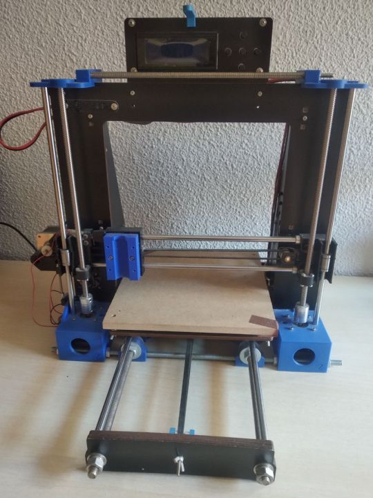
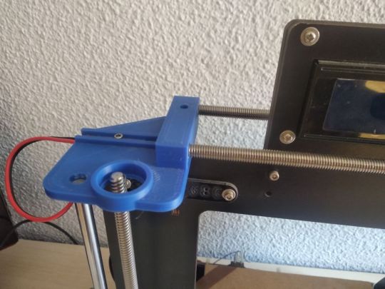
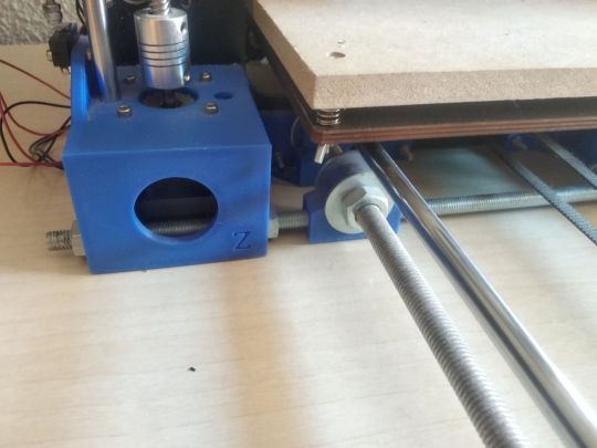
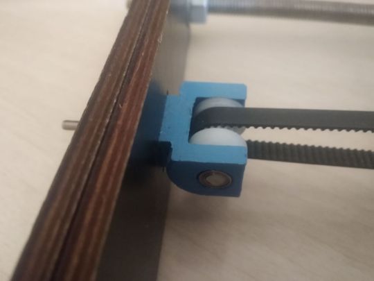
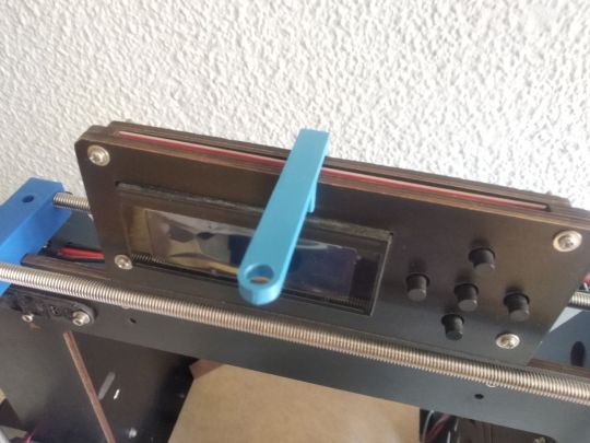


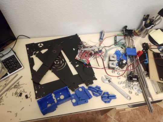
This week's post is not as I expected, but I am excited to do it anyway. I had to disassemble my first printer (from 2018) to make way for the new one that is coming, and it seems like a good time to remember everything I lived with it (and that people do not make my same mistakes) and all the changes I made. Photos 1-3: My first printer was a Prusa i3 clone, super cheap, which as you can expect ... It wasn't a big deal. The structure was made of plywood and that added a lot of vibrations (Z-wobble for those who understand more) to the prints. I tried everything: printing parts to decouple the Z-axis, changing it... But in the end the most effective thing was to reinforce the structure. In 2020, while the confinement due to covid, I participated with my Ender in a project to make equipment for the protection of health personnel, and I decided to fix the Prusa, at that time inoperative, to go faster. That's when I added the iron bars to reinforce the structure, which is what worked. I used 1.5 kg of filament a day making visors, whose photo is lost on my Instagram account. As you can see, I chose blue as the main color for the Prusa, just as for the Ender I have red, because I like to have them decorated uniformly. The new printer will also be red, so it seems that I chose well having red as the basis of my logo. And well, also comment that two of the rods that are seen in the structure are the Z-axe of the printer itself, which I changed them for trapezoidal spindles (no, it did not bring them before, just as I put the union between axes and motor because the one it brought was a piece of shabby plastic). Photos 4-5: Some improvements I made separately. The first is a tensioner for the Y axis (the one it brought did not work) and the second is a guide for the filament I designed. Since the printer had nowhere to leave the filament coil, I had the holder for the coil on a shelf above the printer, and with the guidance I made sure it fell on the extruder. NASA technology, as you see. Photos 6-7: Here we enter electronics/electricity. First, a MOSFET that had to be put in at that time, because if you didn't put it the risk of the hot bed start a fire... Super safe everything. The second thing, as silly as it sounds, is that I put a switch on the printer. No, it did not bring one, the plug cables went directly to the power supply. There was one of the reasons why this printer was so cheap. Photos 8-9: The most observant people will have noticed that the printer does not have an extruder, since I did not use it after COVID, there came a time when I said "what if I transform it into a CNC machine?". And so I did, attaching a Dremel-style rotary tool to it. I think I only used it for the smiley face testing if it worked, but hey, I have fun adapting the hardware and software. Photo 10: And finally... We say goodbye. I plan to reuse all the components for other things, that's why it doesn't taste so bad to disassemble it, but I do have good memories spending hours with this printer. Of course, as much as I have learned with it, I strongly recommend with this type of technology to inform yourself well in advance and invest a little more to make sure you have something in conditions. En español:
El post de esta semana no es como esperaba, pero me hace ilusión hacerlo igualmente. He tenido que desmontar mi primera impresora (de 2018) para dar paso a la nueva que está por llegar, y me parece un buen momento para recordar todo lo que viví con ella (y que la gente no cometa mis mismos errores) y todos los cambios que le hice.
Fotos 1-3: Mi primera impresora fue una Prusa i3 clónica, super baratilla, que como podéis esperar… No era gran cosa. La estructura era de contrachapado y eso añadía muuuchas vibraciones (wobble para quien entienda más) a las impresiones. Probé de todo: a imprimir piezas para desacoplar el eje Z, a cambiárselo… Pero al final lo más efectivo fue reforzar la estructura.
En 2020, en pleno confinamiento por el covid, participé con mi Ender en un proyecto para hacer equipamiento para protección del personal sanitario, y decidí apañar la prusa, en ese momento inoperativa, para ir más rápido. Fue entonces cuando le añadí las barras de hierro para reforzar la estructura, que fue lo que funcionó. Gastaba 1,5 kg de filamento al día haciendo viseras, cuya foto está por ahí perdida en mi cuenta de Instagram.
Como podéis apreciar, elegí el azul como color principal para la Prusa, igual que para la Ender tengo el rojo, porque me gusta tenerlas decoradas uniformemente. La nueva impresora también será roja, así que parece que elegí bien teniendo el color rojo como base de mi logo. Y bueno, comentar también que dos de las varillas que se ven en la estructura son los propios ejes de la impresora, que se los cambié por husillos trapezoidales (no, no traía de antes, igual que le puse yo la unión entre ejes y motor porque la que traía era un trozo de plástico cutre).
Fotos 4-5: Algunas mejoras que hice aparte. La primera es un tensor para el eje Y (el que traía no funcionaba) y la segunda es una guía para el filamento que me diseñé. Como la impresora no tenía donde dejar la bobina de filamento, tenía el soporte para la bobina en una estantería sobre la impresora, y con la guía me aseguraba de que cayese sobre el extrusor. Tecnología de la NASA, vamos.
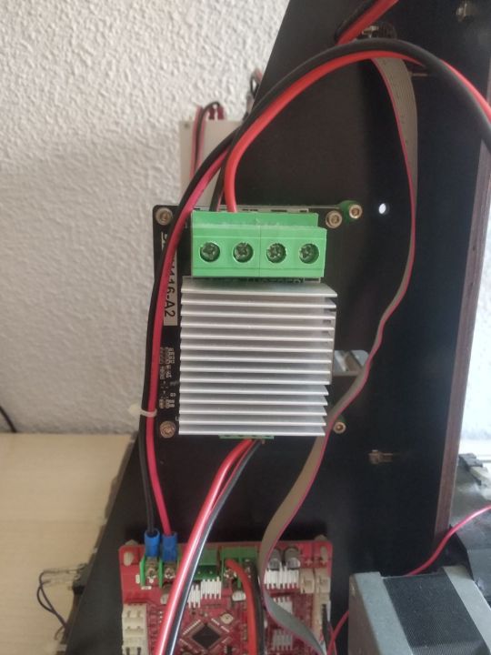
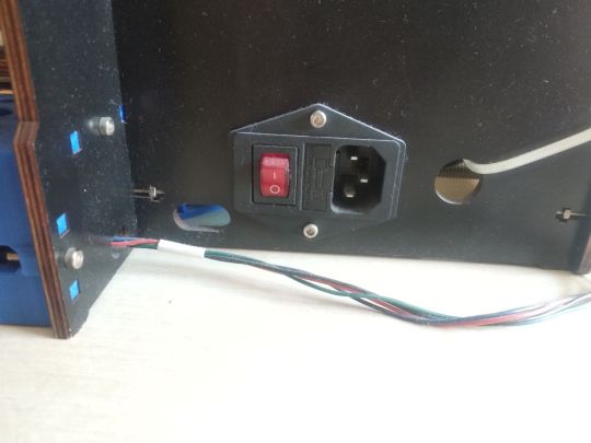
Fotos 6-7: Aquí entramos en electrónica/electricidad. Primero, un MOSFET que había que poner por aquel entonces, porque si no corrías el riesgo de que la cama caliente echase a arder… Super seguro todo. Lo segundo, por tonto que parezca, es que le puse un interruptor a la impresora. Porque no, no traía, los cables del enchufe iban directamente pelados a la fuente de alimentación. Por algo era tan barata esta impresora.
Fotos 8-9: Las personas más observadoras se habrán dado cuenta de que la impresora no tiene extrusor, y es que como no la usaba después de lo del COVID, llegó un momento en el que dije “¿y si la transformo en una máquina CNC?”. Y así lo hice, acoplándole una herramienta giratoria estilo Dremel. Creo que sólo la usé para la carita sonriente de prueba de si funcionaba, pero oye, ¿y lo bien que me lo pasé adaptando el hardware y el software?
Foto 10: Y finalmente… Decimos adiós. Pienso reaprovechar todos los componentes para otras cosas, por eso no me sabe tan mal desmontarla, pero sí que tengo buenos recuerdos echando horas con esta impresora. Eso sí, por mucho que haya aprendido con ella, recomiendo encarecidamente con este tipo de tecnologías informarse bien previamente e invertir un poquito más para asegurarse de tener algo en condiciones.
0 notes
Text
Flotsam and jetsam.
My obsessive checking of classified ads can lead to darkish moments. I sold my Sony 2251 Turntable a long time ago. It is good and rare and I have seen mine pop up on rolling seascape of on-line listings twice. Both were oh dear moments. What went wrong? Has it failed? Is it not in a happy home?
The first was the person I sold it to apparently having a bad turn in his health and offering it for a lot less than he paid for it. I almost got in touch, but no my time with it was past. There are a couple out there and they command good prices. I hoped it was to go to a good new home.
Recently I saw it again. Actually I saw a photo of it as just the tonearm was for sale. It was the Grace 707 from back in the day of high compliance 45khz cartridges for quadraphonic. I did not see it as a parting out, but the Sony originally had an SME 3009 tone arm and the arm board was drilled out for that. If an aficionado had it they may have recognized that and wanted to restore it to an SME. At least that is the story I tell myself. Why else sell just the tonearm?
I have to be really careful. My system has a nice balance and I like where its at. My one itch is a MOSFET power amp. At least I tell myself that. Oh and if a Beogram 4002 came up for a good price I would be hard pressed to resist. I recently saw a Mosfet amp for sale for a hot number. The company that made it rode high for awhile, but is now gone. I have not been able to find a definitive schematic as I always look at those.
I am not mentioning where or the brand as I do not want someone grabbing it before I have convinced myself to not get it. This always makes me feel doubt. Still working on that.
I found photos of the interior which evolved over a few years. Apparent that the large power supply is shared by both sides which is a strike against it. There is lots of room to add capacitors, and a bridge rectifier which is a tick in the good side box. But apparently there is a large circuit board on the power supply on later versions for mysterious reasons. Regulation? Some kind of protection system? If I could get a schematic that described it that would really help. If I bought it I would have to split the power supply as that does really help the image clarity.
And if you dig back through the old day reviews as I do you may find reference to FET haze. I assume it is rather like tube haze and FETs are always being compared to the vacuum tube. Vacuum tubes do add something not in the recording. Call it haze or mist or space whatever it is not quite right.
Audiophile neurosis.
My ARC preamp signal path is all FET where it is not a 6DJ8 tube. That works fine for me.
Old school transistors are still used, and every mosfet amplifier I have looked at still has those in critical places. And there are many respected power amps with no FETS anywhere inside. See I have almost convinced myself.
#Sony 2251#mosfet#amplifiers#sony turntable#grace 707#audiophile neurosis#audiophile#high end audio#tubes vs transistors#audio research preamp
2 notes
·
View notes
Text
The Traction Inverter Market: A Comprehensive Outlook 2022-2032
The global traction inverter market is expected to grow at a compound annual growth rate of 7.6% from 2022 to 2032. Despite Covid-19’s impact on global economic activity, the traction inverter market will continue to experience sustained growth due to its various applications in rail transport and the introduction of reliable and energy-efficient traction inverter products. Market penetration of HVDC systems is predicted to grow in the upcoming years. This, in turn, is expected to stimulate the traction inverter market growth since HVDC systems use advanced traction inverters to convert AC power to DC power.
Furthermore, the growing electric automobile industry due to stringent government regulations on vehicle emissions and better consumer acceptance is expected to drive the traction inverter market growth. The manufacturing of fuel-efficient electric vehicles has compelled carmakers to invest in research and development activities related to the drive systems, batteries, and charging infrastructure. This has further helped improve the adoption rate of electric vehicles.
Download Sample Copy of This Report: https://www.factmr.com/connectus/sample?flag=S&rep_id=8041?VM
Key Companies Profiled
BorgWarner Inc.
Marelli
Mitsubishi Electric Corporation
Denso Corporation
Continental AG
Delphi Technologies
Siemens AG
TOSHIBA CORPORATION
Hitachi, Ltd.
Voith GMbh
Competitive Landscape
There are several prominent manufacturers in the traction inverter market, including BorgWarner Inc., Delphi Technologies, Siemens AG, Mitsubishi Electric Corporation, ABB, and Toshiba Corporation. These manufacturers are keen on forming joint ventures with small-scale players around the world to build an international customer base and gain a larger market share.
A key focus of market players in the Traction Inverter Market is the development of advanced and efficient products. Furthermore, these players are also setting up manufacturing facilities in developing countries for traction inverters.
As a result, major companies are introducing new products to sustain their business in the traction inverter market, which enables them to grow their business in the global traction inverter market. Businesses can gain modest traction in the traction inverter market by offering new categories of traction inverters that target previously untapped customer markets.
Key Segments
By Propulsion :
BEV
HEV
PHEV
Others
By Voltage :
Up to 200V
200 to 900V
900V and above
By Technology :
IGBT
MOSFET
Others
By Vehicle :
Passenger Cars
Commercial Vehicles
Others
By Region :
North America
Latin America
Asia Pacific
MEA
Europe
Get Full Access of Complete Report: https://www.factmr.com/checkout/8041
Questionnaire answered in the Market outlook Report of Traction inverter market include:
What is the key strategy deployed by large players to maximize Traction inverter market growth?
What are the main challenges faced by players in the Traction inverter market Demand?
With the advent of technological advancement, how will the Traction inverter market landscape change over the forecast period?
What does player bring to the table which is unique as a strategy, and is easy to emulate for new investors in the Traction inverter market size?
Contact:
US Sales Office :11140 Rockville Pike Suite 400Rockville,
MD 20852United States
Tel: +1 (628) 251-1583
E-Mail: [email protected]
0 notes